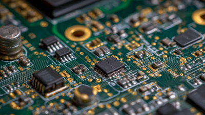

A circuit board may look like a crowded patchwork of copper, ceramic, and tiny packages. Yet each part has a defined job. Resistors limit current. Capacitors store charge and smooth supply noise. Diodes guide current in one direction, while transistors switch or amplify signals. Together, these circuit board components shape how reliably a device performs, from startup to its longest operating day.
Signal-integrity expert Dr. Eric Bogatin teaches engineers to consider how components interact with the signals around them. An editorial summary, not a verbatim quotation, captures that principle: “A component never works alone; its neighbors shape its behavior.” That matters on a real board. A capacitor placed far from a processor may be less effective than one positioned close to its power pins. A connector can also introduce unwanted noise or weaken a signal. The part itself is only part of the story.
This guide explores the top types of circuit board components, what they do, and where engineers commonly use them. It also looks at active and passive parts, connectors, and electromechanical devices. Component names can feel straightforward; choosing the right rating is less so. Voltage, current, temperature, footprint, and tolerances all matter. Even a sensible design can have trade-offs. The aim here is practical clarity, while recognizing that board requirements vary by application.
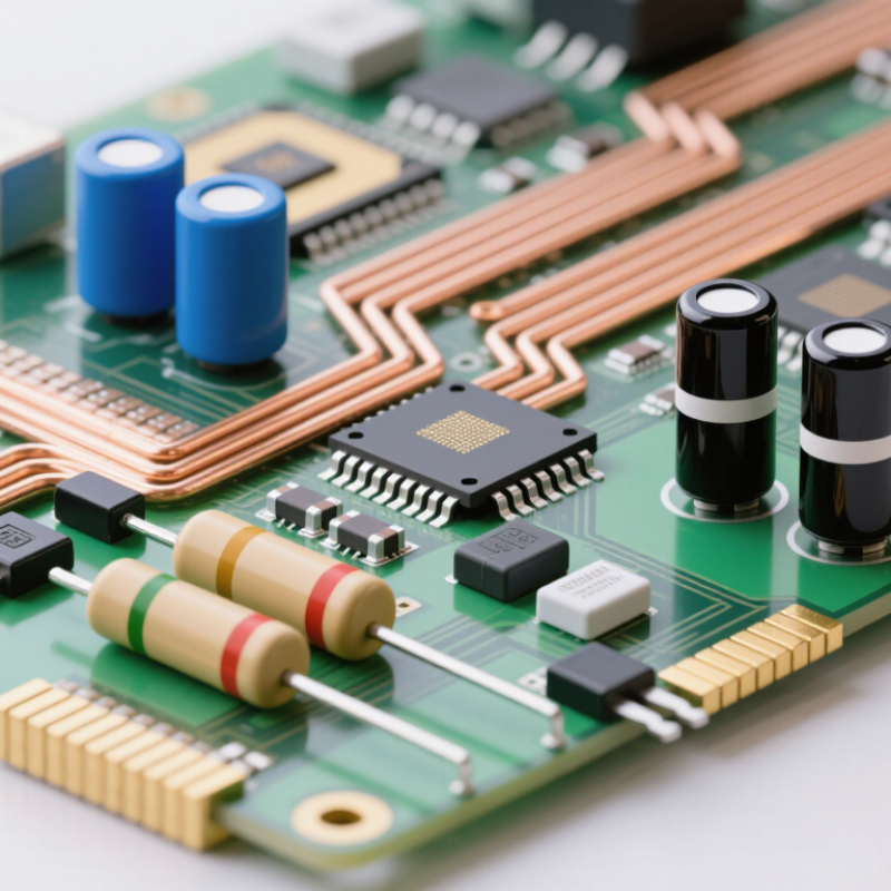
Circuit board components are often grouped as passive, active, or electromechanical parts. The categories help explain what each part does, though real designs can blur the boundaries.
Passive components, such as resistors, capacitors, and inductors, shape current and voltage without adding energy to a signal. A resistor may limit current to an indicator light, while a capacitor can smooth brief voltage changes. Small parts matter. Their values, tolerances, and placement can affect how a board performs, especially in sensitive circuits.
Active components control or amplify electrical signals. Transistors switch loads, while integrated circuits can manage timing, processing, or power conversion. Diodes guide current in one direction and protect circuits from certain voltage spikes; classifications may vary by reference.
Electromechanical components connect electrical behavior with physical movement or contact. Examples include switches, relays, and board-mounted connectors. A relay clicks as its contacts change state. Connectors also need suitable spacing and secure solder joints, since repeated handling can stress them.
The boundary between categories is not always tidy, and a component’s role depends on the circuit around it. Heat changes behavior. Reviewing the schematic, datasheet, and physical footprint together gives a more dependable picture than relying on a category label alone.

Resistors are tiny, but their package choice affects placement density, soldering, and inspection. An EIA 0402 resistor measures about 1.0 × 0.5 mm; a 0603 measures about 1.6 × 0.8 mm. These are component-body dimensions, not pad-to-pad spacing. The metric sizes follow common EIA package-code conventions. IPC-7351B, an industry land-pattern design standard, provides guidance for translating component dimensions into PCB pad layouts.
On a crowded board, the smaller 0402 can free valuable routing space. But tighter spacing also leaves less room for placement tolerance and visual inspection. A 0603 is easier to handle during assembly and may suit prototypes or circuits that need frequent rework. Check the resistor’s datasheet and your assembly house’s process limits before choosing. Package dimensions alone do not guarantee a reliable solder joint.
Tips: Verify body size, pad geometry, and pick-and-place capability together. For a 0402 footprint, inspect the actual layout at high magnification; small pad errors can matter. I’d still question whether every design needs the smaller part. It can save space, yet make rework less forgiving.
Multilayer ceramic capacitors, or MLCCs, are common on circuit boards because they fit into small spaces and respond quickly to changing signals. Their capacitance can range from a few picofarads to several microfarads. Small values often help filter high-frequency noise, while larger values can smooth supply voltage. The right choice also depends on voltage rating, tolerance, temperature behavior, and package size. A marked value is not always the value a circuit delivers under operating conditions.
Inductors work differently: they store energy in a magnetic field and resist rapid changes in current. On a board, they often pair with capacitors in filters and power converters. Their values are measured in henries, not farads, so an inductor is not an MLCC. In practice, the neat schematic can hide real trade-offs. Inductor size, current rating, and resistance all affect performance, and a part that looks suitable on paper may run warm or create unwanted noise. Testing the assembled circuit matters.
Semiconductors give a circuit board its ability to control current and process signals. Diodes typically conduct in one direction, making them useful for rectification, voltage clamping, and polarity protection. A small surface-mount diode may sit beside a power connector, where it helps guard against a reversed supply. Orientation matters: its marked cathode must match the board’s intended footprint.
Transistors act as electronic switches or amplifiers. In a compact package, one may control a motor, drive an indicator, or shape a sensor signal. Integrated circuits combine many functions, from timing and signal conversion to power management. Their JEDEC-standard package outlines help define dimensions and terminal arrangements, making board layouts easier to specify and compare. Still, a familiar outline does not guarantee compatibility. Pin assignments, electrical ratings, thermal limits, and mounting details need checking against the component data sheet.
Look closely at the board. Pin-one marks, tiny polarity bands, and exposed thermal pads can be easy to miss under workshop lighting. Solder joints matter, too; a bridged lead can disrupt an entire circuit. Package standards make identification more orderly, but they do not remove the need for careful inspection. I find package codes useful, yet sometimes incomplete when choosing a replacement. Verify the exact device and footprint before assembly.
Connectors and relays need land patterns that fit both electrical and mechanical demands. IPC-7351, the Generic Requirements for Surface Mount Design and Land Pattern Standard, defines three density levels: Most, Nominal, and Least. These choices balance board space against assembly and inspection clearance.
For a fine-pitch connector, check the lead pitch, pad width, and toe and heel extensions against the component drawing. A footprint that saves space may leave too little room for solder inspection.
Relays often have larger bodies and greater mass than small passive parts. Their pads must suit the terminal geometry, while nearby keepouts should allow the housing and assembly tools to fit. Check the relay’s mounting details too; a land pattern alone does not guarantee resistance to mechanical stress.
Clearance matters. Validate library footprints against the supplier’s package dimensions, then review the assembled board for solder access and placement tolerance.
Test the fit. IPC-7351 provides a consistent starting point, but package variations can still make a standard footprint imperfect. A 3D clearance check and a prototype review can catch those gaps before production.