

Choosing a Pneumatic Conveyor is not simply a matter of matching a machine to a required capacity. The material itself sets important limits. A free-flowing plastic pellet behaves differently from a fine, abrasive powder or a fragile grain. Particle size, moisture, bulk density, and temperature can all affect flow. Details matter. Even a small change in moisture may cause a material to cling to pipe walls or form plugs. Yet these properties are sometimes estimated rather than measured, leaving room for costly surprises.
This guide explains how to compare conveying methods, system layouts, and operating requirements before choosing equipment. It considers dilute-phase and dense-phase conveying, pressure and vacuum systems, pipeline distance, bends, throughput, and receiver placement. It also looks at energy use, dust control, wear, cleaning, and maintenance access. Ask suppliers to assess your actual material and operating conditions, not just a target tonnage. Where possible, request test data or a material trial. No checklist removes every uncertainty. Real plants change, and early estimates are not always right. A practical choice balances performance with operating cost and future flexibility. The aim is a system that moves material reliably, fits the available space, and remains manageable after installation—not merely one that looks suitable on paper.
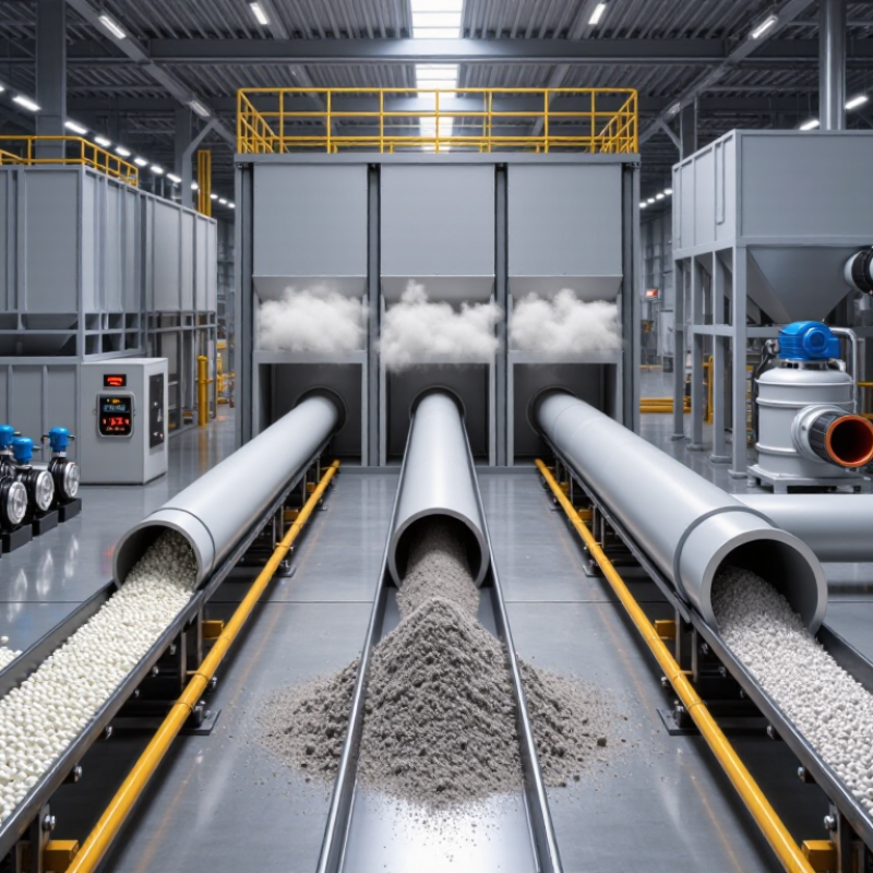
A pneumatic conveyor should be matched to the material before its capacity is selected. Record particle size, bulk density, moisture, temperature, and abrasiveness. Note whether the product is fragile, dusty, or prone to clumping. These details affect air velocity, pipe diameter, and the risk of blockages or product damage. A dry, free-flowing powder behaves very differently from damp flakes.
Measure the required throughput in kilograms or tonnes per hour, and distinguish average demand from short peaks. A system sized only for the average may struggle when a hopper empties quickly or production speeds up. Include conveying distance, vertical lifts, bends, and the number of feed and discharge points. A short route with several tight bends can be harder to handle than its length suggests. Small details matter.
Get representative material samples tested when possible, especially if the product is abrasive, friable, or inconsistent. Ask for performance assumptions, such as operating hours and expected feed rate, to be documented. These numbers are rarely perfect. It is easy to overestimate capacity and overlook how moisture changes after storage. Recheck the estimates against actual production records before choosing a conveying method or equipment size.
How to Choose a Pneumatic Conveyor for Your Needs?
Choose Between Dilute-Phase and Dense-Phase Conveying
Dilute phase suspends particles in a fast-moving air stream. It suits many free-flowing powders and granules, especially when flexible routing matters. Dense phase moves material more slowly, often in plugs or compact slugs. It can be gentler on fragile particles and abrasive products. The difference is visible at the line: dilute systems keep particles airborne, while dense systems may move them in intermittent, fuller-bore batches. That matters.
Klinzing et al. report typical conveying velocities of roughly 15–30 m/s for dilute phase and 1–8 m/s for dense phase in Pneumatic Conveying of Solids (3rd edition, 2010). These are reference ranges, not guaranteed design values; particle size, moisture, pipeline length, and bends can shift them. For example, a friable granule passing repeated elbows may benefit from a lower-velocity design, while a long route with variable feed can make dense-phase flow harder to stabilize. Check pressure, air demand, and material degradation in a conveying trial where possible. A neat calculation can still miss a sticky batch. Ask suppliers for test data using your actual material, then compare throughput and wear against your operating needs.
| Selection factor | Dilute-phase conveying | Dense-phase conveying | What to consider |
|---|---|---|---|
| Typical conveying velocity | Relatively high; often approximately 15–30 m/s, depending on the material and system design. | Relatively low; often approximately 2–10 m/s, depending on the material and conveying method. | These are indicative ranges, not design limits. The required velocity depends on particle size, density, pipe layout, and the risk of settling or degradation. |
| Typical solids loading | Lower solids-to-air loading; commonly used when substantial airflow is acceptable. | Higher solids-to-air loading; more material is conveyed relative to the air used. | Loading ratios and phase definitions vary between applications and suppliers. Confirm them through material testing and system design. |
| Material characteristics | Often suitable for free-flowing, robust powders and granules that tolerate higher conveying velocities. | Often considered for fragile, abrasive, or dust-sensitive materials that benefit from gentler handling. | Assess particle size distribution, bulk density, moisture, cohesiveness, abrasiveness, and friability before selecting a conveying mode. |
| Product handling | Higher particle velocity can increase attrition, breakage, and wear, particularly at bends. | Lower velocities can reduce impact and erosion, although plugs or poor operating conditions can still damage product or equipment. | For fragile products or strict particle-size requirements, request conveying trials using representative material. |
| Air and energy considerations | Typically requires higher airflow and can involve higher air velocity through the conveying line. | Typically uses lower conveying air velocity and higher solids loading; pressure requirements depend on the system configuration. | Compare total system energy, including the air mover, feeder, filtration, and controls—not airflow or pressure alone. |
| Equipment and operation | Often has a comparatively straightforward layout, but needs reliable feeding and dust collection. | May require specialized feeding, pressure control, and conveying-cycle controls, especially for batch operation. | Consider operator experience, maintenance access, process continuity, and the complexity of the feeding arrangement. |
| Common application priorities | Good fit when flexible routing, simpler operation, and robust product handling are key priorities. | Good fit when limiting product damage, reducing line wear, or handling material at a higher solids loading is important. | Neither phase is universally better. The right choice depends on the material, throughput, route, and operating constraints. |
| Information needed for final design | Required throughput; conveying distance and elevation; pipe bends and diameter; material properties; operating schedule; allowable degradation; and available air, power, and space. | Use these inputs for a system assessment and, where appropriate, material testing or a pilot trial. | |
Design note: Velocity and loading figures are typical screening guidance only. Actual operating values vary with material properties, pipeline geometry, feeder design, and system configuration. A qualified pneumatic-conveying engineer should verify the final design.
A pneumatic conveyor should follow the real process layout, not just the shortest line on a drawing. Map where material enters, where it must go, and which areas need clear access. A route with several tight bends may look compact but can increase wear, pressure loss, and maintenance work. Space is not neutral.
For a long, branching route with multiple pickup points, a dilute-phase system may offer useful flexibility for free-flowing materials. If the product is fragile, abrasive, or needs to move at a controlled rate, dense-phase conveying may be worth evaluating. Vertical lifts, overhead pipework, and limited floor space can change the decision. So can the location of filters, receivers, and discharge points. Plan for access.
A layout review should include pipe length, bend radius, elevation changes, and available space for equipment and maintenance. Check how operators will reach inspection points and clear a blockage safely. A route that works on paper can be awkward to service once pipes are installed above a production line. That detail matters. Material tests and a site survey can help confirm whether the selected conveying method fits the actual process. Real layouts are rarely perfect, so allow room for adjustments.
Evaluate Air Supply, Filtration, and System Controls
A reliable pneumatic conveyor starts with the air available at the point of use. Check flow rate and pressure during peak demand, not just the compressor’s nameplate rating. Long pipes, elbows, and shared equipment can reduce pressure before air reaches the conveying line. Ask the supplier to assess your material, route, and expected throughput together. One number is not enough.
Filtration affects both equipment life and product quality. Dust, water, or oil in the air can cause blockages, wear, or contamination. Specify filtration suited to the material and operating environment, and check how often elements need replacing. Filters also create pressure loss as they load. That matters. A filter that looks adequate on paper may restrict airflow after months of use, so include maintenance access in the layout.
Controls should help operators see problems early. Pressure and airflow sensors can flag a developing blockage before the line stops. Interlocks can sequence startup and shutdown, while clear alarms help staff respond without guesswork. Keep control settings adjustable, but protect critical limits from casual changes. More automation is not always better. A simpler control scheme may be easier to maintain, though it can provide less diagnostic detail. Review that trade-off with the people who will run and service the system.
How to Choose a Pneumatic Conveyor for Your Needs?
Compare Operating Costs, Maintenance, and Safety Needs
A pneumatic conveyor can save floor space, but its energy demand depends on the material, distance, and conveying method. Dilute-phase systems move material quickly through a large volume of air; dense-phase systems use less air but may need higher pressure. Ask suppliers to estimate power use at your actual throughput, not just peak capacity. That detail matters.
Operating costs include electricity, filters, replacement pipe bends, and any downtime needed to clear blockages. Fine powders can wear elbows faster, especially where the flow changes direction. Dense-phase equipment may reduce abrasion for some materials, but it is not automatically cheaper to run. Compare realistic annual costs, including labor and spare parts. Estimates can miss things.
Maintenance needs should match your team’s skills and schedule. Check how easily workers can inspect filters, access rotary valves, and remove accumulated material. Ask how often seals and bearings typically need replacement under comparable conditions. A neat brochure will not tell you everything; operating conditions vary, and estimates deserve scrutiny.
Safety planning starts with the material itself. Dust may require an assessment for combustible-dust risks, while pressure systems need suitable relief devices and isolation procedures. Consider grounding, leak detection, guarded moving parts, and safe access for maintenance. Requirements vary by site and material, so have qualified engineers review the design before installation.
Compare common conveying approaches using indicative relative-burden scores. A higher score means greater planning burden, not a measured cost or safety risk.
Dilute-phase systems typically move material at higher air velocities, which can increase energy use and wear. Dense-phase systems convey at lower velocities but may require more specialized pressure and control arrangements. Vacuum systems need careful attention to filtration and dust containment. Actual requirements depend on the material, conveying distance, throughput, and operating conditions; assess combustible-dust hazards for any system handling combustible materials.

